Title here
Summary here
Now let’s try understanding
how to effectively update,
using RAUC,
even the FIP that gets executed by the TFA,
that is, the binary that contains
UBOOT and OPTEE together with their device trees.
It does not make sense to directly replace the
FIP used by the TFA,
because in the event of errors during installation
or errors in the code that is loaded,
we risk ending up with an unbootable system,
since only TFA would be able to start,
but on its own it is not useful enough.
It might be able to load Linux
on its own, but that’s another story.
Fortunately, the multi-bank update mechanism
is already present in TFA.
There is even an
official document
from ARM that explains how this mechanism works.
Let’s go.
In the TFA code,
we find the initialization function of stage bl2,
which is the entrypoint of the bootloader,
and we see:
101#if PSA_FWU_SUPPORT
102	if (plat_fwu_is_enabled()) {
103		fwu_init();
104	}
105#endif /* PSA_FWU_SUPPORT */
this function is defined in:
268/*******************************************************************************
269 * Load verified copy of FWU metadata image kept in the platform NV storage
270 * into local FWU metadata structure.
271 * Also, update platform I/O policies with the offset address and length of
272 * firmware-updated images kept in the platform NV storage.
273 ******************************************************************************/
274void fwu_init(void)
275{
276	/* Load FWU metadata which will be used to load the images in the
277	 * active bank as per PSA FWU specification
278	 */
279	int result = fwu_metadata_load(FWU_METADATA_IMAGE_ID);
280
281	if (result != 0) {
282		WARN("loading of FWU-Metadata failed, "
283		     "using Bkup-FWU-Metadata\n");
284
285		result = fwu_metadata_load(BKUP_FWU_METADATA_IMAGE_ID);
286		if (result != 0) {
287			ERROR("loading of Bkup-FWU-Metadata failed\n");
288			panic();
289		}
290	}
291
292	is_metadata_initialized = true;
293
294	plat_fwu_set_images_source(&metadata);
295}
this one calls a metadata load method,
which in turns identifies the partition having
type code (GUID)
GUID=8A7A84A0-8387-40F6-AB41-A8B9A5A60D23,
as of ARM specification.
This and other constants are declared in:
268#define EFI_GUID(a, b, c, d0, d1, d2, d3, d4, d5, d6, d7) \
269	{ (a) & 0xffffffffU,		\
270	  (b) & 0xffffU,			\
271	  (c) & 0xffffU,			\
272	  { (d0), (d1), (d2), (d3), (d4), (d5), (d6), (d7) } }
273
274#define FWU_METADATA_GUID \
275	EFI_GUID(0x8A7A84A0U, 0x8387U, 0x40F6U, \
276		 0xABU, 0x41U, 0xA8U, 0xB9U, 0xA5U, 0xA6U, 0x0DU, 0x23U)
277
278#define NULL_GUID \
279	EFI_GUID(0x00000000U, 0x0000U, 0x0000U, 0x00U, 0x00U, \
280		 0x00U, 0x00U, 0x00U, 0x00U, 0x00U, 0x00U)
The interesting thing, however, is the call to the function
plat_fwu_set_images_source
which is specific to the platform, in our case ST.
In fact, its definition can be found inside the folder
plat/st.
The following file contains many of the st specific functions
that are common to the MP1 and MP2 series.
Let’s take a look:
857void plat_fwu_set_images_source(const struct fwu_metadata *metadata)
858{
859	unsigned int i;
860	uint32_t boot_idx;
861	const partition_entry_t *entry __maybe_unused;
862	const struct fwu_image_entry *img_entry;
863	const void *img_type_guid;
864	const void *img_guid;
865	io_block_spec_t *image_spec;
866	const uint16_t boot_itf = stm32mp_get_boot_itf_selected();
867
868	boot_idx = plat_fwu_get_boot_idx();
869	assert(boot_idx < NR_OF_FW_BANKS);
870	VERBOSE("Selecting to boot from bank %u\n", boot_idx);
871
872	img_entry = (void *)&metadata->fw_desc.img_entry;
873	for (i = 0U; i < NR_OF_IMAGES_IN_FW_BANK; i++) {
874		img_type_guid = &img_entry[i].img_type_guid;
875
876		img_guid = &img_entry[i].img_bank_info[boot_idx].img_guid;
877
878		image_spec = stm32_get_image_spec(img_type_guid);
879		if (image_spec == NULL) {
880			ERROR("Unable to get image spec for the image in the metadata\n");
881			panic();
882		}
883
884		switch (boot_itf) {
885#if (STM32MP_SDMMC || STM32MP_EMMC)
886		case BOOT_API_CTX_BOOT_INTERFACE_SEL_FLASH_SD:
887		case BOOT_API_CTX_BOOT_INTERFACE_SEL_FLASH_EMMC:
888			entry = get_partition_entry_by_guid(img_guid);
889			if (entry == NULL) {
890				ERROR("No partition with the uuid mentioned in metadata\n");
891				panic();
892			}
893
894			image_spec->offset = entry->start;
895			image_spec->length = entry->length;
896			break;
897#endif
898#if STM32MP_SPI_NOR
899		case BOOT_API_CTX_BOOT_INTERFACE_SEL_FLASH_NOR_SPI:
900			if (guidcmp(img_guid, &STM32MP_NOR_FIP_A_GUID) == 0) {
901				image_spec->offset = STM32MP_NOR_FIP_A_OFFSET;
902			} else if (guidcmp(img_guid, &STM32MP_NOR_FIP_B_GUID) == 0) {
903				image_spec->offset = STM32MP_NOR_FIP_B_OFFSET;
904			} else {
905				ERROR("Invalid uuid mentioned in metadata\n");
906				panic();
907			}
908			break;
909#endif
910#if (STM32MP_RAW_NAND || STM32MP_SPI_NAND)
911		case BOOT_API_CTX_BOOT_INTERFACE_SEL_FLASH_NAND_FMC:
912		case BOOT_API_CTX_BOOT_INTERFACE_SEL_FLASH_NAND_SPI:
913			if (guidcmp(img_guid, &STM32MP_NAND_FIP_A_GUID) == 0) {
914				image_spec->offset = STM32MP_NAND_FIP_A_OFFSET;
915			} else if (guidcmp(img_guid, &STM32MP_NAND_FIP_B_GUID) == 0) {
916				image_spec->offset = STM32MP_NAND_FIP_B_OFFSET;
917			} else {
918				ERROR("Invalid uuid mentioned in metadata\n");
919				panic();
920			}
921			break;
922#endif
923#if STM32MP_HYPERFLASH
924		case BOOT_API_CTX_BOOT_INTERFACE_SEL_HYPERFLASH_OSPI:
925			if (guidcmp(img_guid, &STM32MP_HYPERFLASH_FIP_A_GUID) == 0) {
926				image_spec->offset = STM32MP_HYPERFLASH_FIP_A_OFFSET;
927			} else if (guidcmp(img_guid, &STM32MP_HYPERFLASH_FIP_B_GUID) == 0) {
928				image_spec->offset = STM32MP_HYPERFLASH_FIP_B_OFFSET;
929			} else {
930				ERROR("Invalid uuid mentioned in metadata\n");
931				panic();
932			}
933			break;
934#endif
935		default:
936			panic();
937			break;
938		}
939	}
940}
We see that depending on which interface was used
to boot (SD card, eMMC, NAND flash, etc.),
different methods are used to locate
the metadata partition we are interested in.
Within this, there is another interesting function (plat_fwu_get_boot_idx)
that is part of the API that a new platform must implement in order to
correctly use the fwu driver.
This is defined in the same file, just a little further up:
775#if PSA_FWU_SUPPORT
776/*
777 * In each boot in non-trial mode, we set the BKP register to
778 * FWU_MAX_TRIAL_REBOOT, and return the active_index from metadata.
779 *
780 * As long as the update agent didn't update the "accepted" field in metadata
781 * (i.e. we are in trial mode), we select the new active_index.
782 * To avoid infinite boot loop at trial boot we decrement a BKP register.
783 * If this counter is 0:
784 *     - an unexpected TAMPER event raised (that resets the BKP registers to 0)
785 *     - a power-off occurs before the update agent was able to update the
786 *       "accepted' field
787 *     - we already boot FWU_MAX_TRIAL_REBOOT times in trial mode.
788 * we select the previous_active_index.
789 */
790uint32_t plat_fwu_get_boot_idx(void)
791{
792	/*
793	 * Select boot index and update boot counter only once per boot
794	 * even if this function is called several times.
795	 */
796	static uint32_t boot_idx = INVALID_BOOT_IDX;
797	int err = 0;
798
799	if (boot_idx == INVALID_BOOT_IDX) {
800		const struct fwu_metadata *data = fwu_get_metadata();
801		uint32_t bootcount = 0;
802
803		boot_idx = data->active_index;
804
805		switch (data->bank_state[boot_idx]) {
806		case FWU_BANK_STATE_ACCEPTED:
807			err = stm32_set_max_fwu_trial_boot_cnt();
808			break;
809		case FWU_BANK_STATE_VALID:
810			err = stm32_get_and_dec_fwu_trial_boot_cnt(&bootcount);
811			if (err == 0) {
812				if (bootcount == 1U) {
813					WARN("Trial FWU fails %u times\n",
814					     (FWU_MAX_TRIAL_REBOOT - 1U));
815					boot_idx = fwu_get_alternate_boot_bank();
816				} else if (bootcount == 0U) {
817					WARN("Trial backup register empty : set max boot count\n");
818					err = stm32_set_max_fwu_trial_boot_cnt();
819				} else {
820					VERBOSE("Trial FWU: %u\n",
821						FWU_MAX_TRIAL_REBOOT - bootcount);
822				}
823			}
824			break;
825		case FWU_BANK_STATE_INVALID:
826		default:
827			ERROR("The active bank(%u) of the platform is in Invalid State.\n",
828			      boot_idx);
829			boot_idx = fwu_get_alternate_boot_bank();
830			err = stm32_clear_fwu_trial_boot_cnt();
831			break;
832		}
833
834		if (err != 0) {
835			ERROR("%s: Bkp register access failed. Bank state: %d\n",
836				__func__, data->bank_state[boot_idx]);
837			panic();
838		}
839	}
840
841	return boot_idx;
842}
Here we can see exactly where the logic
that defines the actions to be taken
depending on the read bank_state is implemented.
We see that a mix of generic functions
from the fwu driver
and ST specific functions are used:
799if (boot_idx == INVALID_BOOT_IDX) {
800	const struct fwu_metadata *data = fwu_get_metadata();
801	uint32_t bootcount = 0;
802
803	boot_idx = data->active_index;
804
805	switch (data->bank_state[boot_idx]) {
806	case FWU_BANK_STATE_ACCEPTED:
807		err = stm32_set_max_fwu_trial_boot_cnt();
808		break;
809	case FWU_BANK_STATE_VALID:
810		err = stm32_get_and_dec_fwu_trial_boot_cnt(&bootcount);
811		if (err == 0) {
812			if (bootcount == 1U) {
813				WARN("Trial FWU fails %u times\n",
814						(FWU_MAX_TRIAL_REBOOT - 1U));
815				boot_idx = fwu_get_alternate_boot_bank();
816			} else if (bootcount == 0U) {
817				WARN("Trial backup register empty : set max boot count\n");
818				err = stm32_set_max_fwu_trial_boot_cnt();
819			} else {
820				VERBOSE("Trial FWU: %u\n",
821					FWU_MAX_TRIAL_REBOOT - bootcount);
822			}
823		}
824		break;
For instance:
fwu_get_alternate_boot_bank()
It’s interesting because, in addition to simply reading “previous_active_state”, it also checks whether this is “accepted” and, if not, it searches for a different index associated with a “valid or accepted bank_state”.
stm32_set_max_fwu_trial_boot_cnt()
Same as the other STM functions highlighted, this one interacts with the “trial_boot_cnt” register, which is located in a protected memory area and is not accessible by programs in the normal world. If we try to do so, we will see that the entire system goes into a fault due to an error generated by optee.
Another very important thing is that the metadata we get from the function
const struct fwu_metadata *data = fwu_get_metadata();
is a pointer to const struct, therefore read-only.
If we try to modify its fields,
the compiler will throw an error.
To solve the problem, we cannot
cast it to a pointer of struct fwu_metadata
as it is not allowed.
The solution would be to redefine that
struct throughout the code,
but besides being a huge pain in the ass,
it is also extremely inadvisable.
So, since we want to be able to modify the data in that struct, let’s look for another way.
Let me introduce you to the legendary OPTEEE. Just kidding, I hated it with all my heart.
Before we start cursing about that, though,
we need to talk about something else.
Remember the protected memory area? I hope so,
anyway, we can figure out its location by exploring
one of the stm functions that interacts with
the trial_boot_cnt:
717int stm32_set_max_fwu_trial_boot_cnt(void)
718{
719	struct nvmem_cell fwu_info_cell = {};
720
721	int ret = stm32_get_fwu_info_cell(&fwu_info_cell);
722
723	if (ret != 0) {
724		return ret;
725	}
726
727	return stm32_nvmem_cell_clrset(&fwu_info_cell, FWU_INFO_CNT_MSK,
728				       (FWU_MAX_TRIAL_REBOOT << FWU_INFO_CNT_OFF) &
729				       FWU_INFO_CNT_MSK);
730}
Where, to keep it short,
stm32_get_fwu_info_cell(&fwu_info_cell)
looks in the device tree,
the one we use to compile the TFA,
for the boot-info node
that has a nvmem-cell linked to fwu-info.
This last one redirects to the fwu_info node
which itslef is defined in the nvram
of the tamp
441tamp: tamp@46010000 {
442	compatible = "st,stm32mp25-tamp";
443	reg = <0x46010000 0x400>;
444	clocks = <&rcc CK_BUS_RTC>;
445	interrupts = <GIC_SPI 14 IRQ_TYPE_LEVEL_HIGH>;
446	#address-cells = <1>;
447	#size-cells = <1>;
448	ranges;
449
450	nvram: nvram@46010100 {
451		compatible = "st,stm32mp25-tamp-nvram";
452		#address-cells = <1>;
453		#size-cells = <1>;
454		reg = <0x46010100 0x200>;
455
456		stop2_entrypoint: tamp-bkp@2c {
457			reg = <0x2c 0x4>;
458		};
459		fwu_info: tamp-bkp@c0 {
460			/* see firmware update info feature */
461			reg = <0xc0 0x4>;
462		};
463		boot_mode: tamp-bkp@180 {
464			reg = <0x180 0x4>;
465		};
466
467	};
468
469	boot_info: boot-info {
470		compatible = "st,stm32mp-bootinfo";
471		nvmem-cells = <&boot_mode>, <&fwu_info>, <&stop2_entrypoint>;
472		nvmem-cell-names = "boot-mode", "fwu-info", "stop2-entrypoint";
473	};
474};
That was quite a torture, anyway,
from this we can figure out the memory address
we were looking for,
all that is needed is to
calculate the offset from the beginning of the
nvram node.
Be careful though, as
if we try dumping the first byte
of the tamp memory from a uboot console,
we would see a fault generated by optee
and the system would become unusable.
At least until the watchdog kicks in (if present).
STM32MP>md.b 0x46010000 1
E/TC:0   stm32_iac_itr:192 IAC exceptions \[159:128\]: 0x1000000
E/TC:0   stm32_iac_itr:197 IAC exception ID: 152
E/TC:0   Panic at /usr/src/debug/optee-os/4.0.0-stm32mp/core/drivers/firewall/stm32_iac.c:212 <stm32_iac_itr>
E/TC:0   TEE load address @ 0x82000000
E/TC:0   Call stack:
E/TC:0    0x82007fa0
E/TC:0    0x820441c0
E/TC:0    0x8202de1c
E/TC:0    0x82041c40
E/TC:0    0x8201451c
Where
	   E/TC
severity --'  '-- component
The main severity levels are:
E ErrorW WarningI InfoD DebugThe main components are:
TC Tee CoreTA Trusted ApplicationAnd the logs are displayed based on the log level
that OPTEE got compiled with.
For more details check the official OPTEE documentation
on how to analyze dumps.
Wrapping this up, we now know that TFA is configured to give us information about which FIP index was used to start UBOOT, and we also know where this is located. Now we need to understand how to read and write this value, possibly both in UBOOT and in Linux.
Reference Manual ST RM0457 sezione 75
Il TAMP è una periferica che blocca accessi non autorizzati
alla memoria del dispositivo.
È un dispositivo hardware, non software, e quindi
blocca qualsiasi tipo di accesso fisico/elettronico.
Al suo interno ospita i Backup Registers,
utilizzati per scambiare informazioni tra i vari stage
della bootchain.
For further details, check the ST wiki article.
The TAMP consists of 128 32-bit registers
divided into:
TAMP_SECCFGR secure configuration registersTAMP_BKPxR backup registersIt is divided into 3 zones:
Each zone is subdivided into various RIF,
depending on which core has access or not,
where:
RIF0 cortex a35 or m33 (trusted domain)RIF1 cortex a35RIF2 cortex m33A detailed drawing is available on the ST wiki.
The nvram houses the backup registers,
which are low-power non-volatile memory areas.
The nvram contains 128 registers,
out of the total of 256 of the tamp.
To encapsulate this information
and use it within
multiple software components
the device tree is used,
as seen previously
within the TFA:
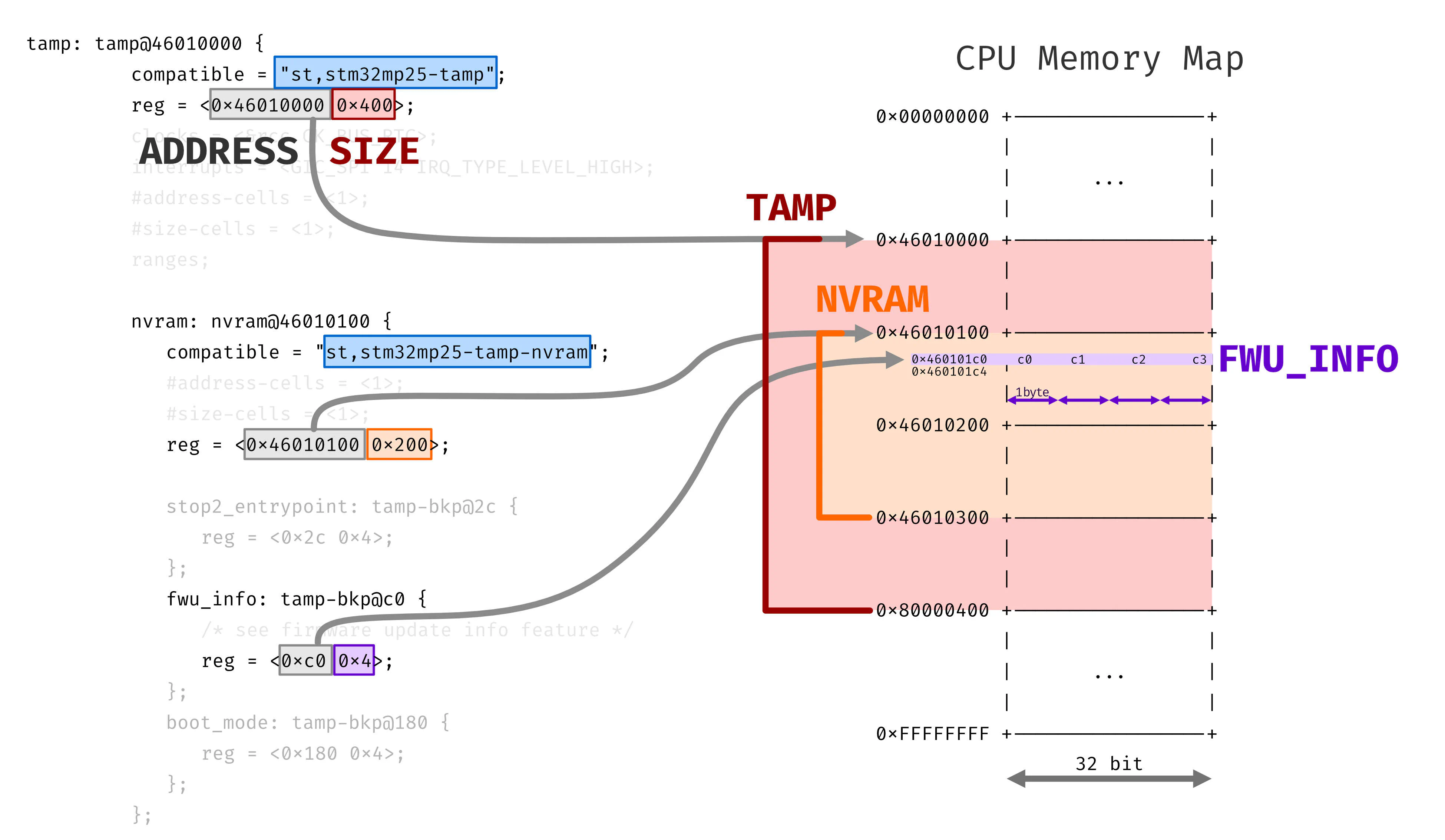
In the device tree, the string compatible
defines the driver that will actually be
used by the software in question
to interact with the memory area.
Thus defining the meaning of
the reg parameter.
This usually corresponds to
the memory address and
the data size.
In the case of nvram, it should be noted that
the address is meant to be absolute,
while for the individual backup registers
it is relative to the beginning
of nvram, thus resulting in an offset.
We can confirm this by fact checking the data found in the ST table.
boot_mode: tamp-bkp@180 {
	reg = <0x180 0x4>;
};
ADDRESS = 0x180 (bytes hex) = 384 (bytes dec)
SIZE = 4 (bytes hex) = 4 (bytes dec)
the register number is ADDRESS in decimal form
divided by the size in bytes of a register
REG_NUMBER = 384 / 4 = 96 decand in the table we actually see:
TAMP_BKP96R = BOOT_MODE con permessi Zone3-RIF1and even this other one checks out:
fwu_info: tamp-bkp@c0 {
	/* see firmware update info feature */
	reg = <0xc0 0x4>;
};
ADDRESS = 0xc0 (bytes hex) = 192 (bytes dec)
SIZE = 4 (bytes hex) = 4 (bytes dec)
the register number is ADDRESS in decimal form
divided by the size in bytes of a register
REG_NUMBER = 192 / 4 = 48 decTAMP_BKP48R = FWU_INFO con permessi Zone2-RIF1We can therefore infer the permissions:
Zona 2 => Read non secure, Write secure
RIF1   => cortex a35
This register allows
writing only for SecureWorld,
but reading for NormalWorld,
so both from UBOOT and Linux
(if the request is made from the A35 core).
F A N T A ST I C
Okay, so now we know we can read that register. But what values should we expect? Going back to the TFA code, we see it in a function that is called to set the boot_index, namely:
665int stm32_fwu_set_boot_idx(void)
666{
667	struct nvmem_cell fwu_info = {};
668	int ret = 0;
669
670	uint32_t clear = FWU_INFO_IDX_MSK;
671	uint32_t set = (plat_fwu_get_boot_idx() << FWU_INFO_IDX_OFF) &
672		       FWU_INFO_IDX_MSK;
673
674	ret = stm32_get_fwu_info_cell(&fwu_info);
675	if (ret != 0) {
676		return ret;
677	}
678
679	return stm32_nvmem_cell_clrset(&fwu_info, clear, set);
680}
Focusing on the values of clear and set, let’s find where these definitions got declared:
61/* Layout for fwu update information. */
62#define FWU_INFO_IDX_MSK		GENMASK(3, 0)
63#define FWU_INFO_IDX_OFF		U(0)
64#define FWU_INFO_CNT_MSK		GENMASK(7, 4)
65#define FWU_INFO_CNT_OFF		U(4)
aaaaand by looking at the declaration
of the GENMASK macro,
wee see that it creates a 32 or 64 bit word
(depending on the SOC architecture)
with 1s only between the two given positions, included.
31/*
32 * Create a contiguous bitmask starting at bit position @l and ending at
33 * position @h. For example
34 * GENMASK_64(39, 21) gives us the 64bit vector 0x000000ffffe00000.
35 */
36#if defined(__LINKER__) || defined(__ASSEMBLER__)
37#define GENMASK_32(h, l) \
38	(((0xFFFFFFFF) << (l)) & (0xFFFFFFFF >> (32 - 1 - (h))))
39
40#define GENMASK_64(h, l) \
41	((~0 << (l)) & (~0 >> (64 - 1 - (h))))
42#else
43#define GENMASK_32(h, l) \
44	(((~UINT32_C(0)) << (l)) & (~UINT32_C(0) >> (32 - 1 - (h))))
45
46#define GENMASK_64(h, l) \
47	(((~UINT64_C(0)) << (l)) & (~UINT64_C(0) >> (64 - 1 - (h))))
48#endif
49
50#ifdef __aarch64__
51#define GENMASK				GENMASK_64
52#else
53#define GENMASK				GENMASK_32
54#endif
So, the boot_index value is defined in the first 4 bits of the register and, similarly, the boot_count value is defined in the next 4 bits of the register.
From a uboot shell, we can perform a 4-byte memory dump starting from the register address:
STM32MP> md.b 0x460101C0 4
460101c0: 40 00 00 00
or using a single “long” memory dump (4 bytes):
STM32MP> md.l 0x460101C0 1
460101c0: 00000040
Being careful of the byte ordering, we take the first byte (8 bits) and cut it in half:
      4 0
cnt --' '-- idx

cnt = 4 hex = 4 dec  --> available try number
idx = 0 hex = 0 dec --> FIP slot index used to bootNow we just need to implement a UBOOT command that allows us to read this memory area and print useful information to the screen. We can then use this in our UBOOT scripts to understand the state in which the TFA left us in.
For a slightly more elegant method, the command could look up the memory area by reading the device tree and calculating the exact address.
Another alternative is to implement this process as a Trusted Application that can be used within OPTEE and then calling the OPTEE server from UBOOT or Linux.
Leaving aside for the time being how to make these changes using Yocto, to add a command in UBOOT, we simply need to add the following files:
.h in include/.c in cmd/and insert them into the compilation chain, by adding
a KCONFIG variable that controls
the compilation via MAKE.
That is, by making the following changes to the
Kconfig and Makefile files inside the cmd/ folder.
173config CMD_FWU_METADATA
174	bool "fwu metadata read"
175	depends on FWU_MULTI_BANK_UPDATE
176	help
177	  Command to read the metadata and dump it's contents
178
179config CMD_FWU_CUSTOM
180	bool "custom fwu command"
181	depends on FWU_METADATA
182	help
183	  Custom command to manage firmware updates
184
185config CMD_LICENSE
186	bool "license"
187	select BUILD_BIN2C
188	help
189 Print GPL license text90obj-$(CONFIG_CMD_FUSE) += fuse.o
91obj-$(CONFIG_CMD_FWU_METADATA) += fwu_mdata.o
92obj-$(CONFIG_CMD_FWU_CUSTOM) += fwu_custom.o
93obj-$(CONFIG_CMD_GETTIME) += gettime.o
94obj-$(CONFIG_CMD_GPIO) += gpio.oThe important thing is that the .h and .c files
all have the same name and that
we use this name in the Makefile to indicate
the .o file resulting from compilation.
For example, we can use fwu_custom as the name,
while respecting the extensions of the various files.
uboot command code

TA optee implementation